Start Solidworks if it's not already open, and select File>New>Part
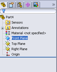
It should open to a blank template with the three planes and origin showing.

In this practice session you'll be making a 5 inch long piece of 3/4 x .049 tubing.
You first need to sketch out a 2D profile of the tube. To start sketching, select a plane. In this practice guide, I recommend the Front plane.

Select the Front plane by clicking the border of it, OR through the Feature Manager on the left-hand side of the screen.
 Now click the Sketch Icon near the top of the screen to start sketching on the Front plane.
It should automatically bring you to a Normal view of the Front plane.
Like so.

Where the two other planes intersect is the Origin.
Using the Circle tool, sketch a circle from the Origin.

Make sure you start by clicking the Origin to insure the circle's center is Coincident with it.
Once the circle is sketched, you need to define it by giving it a dimension(size)
Select the Smart Dimension tool(Next to Sketch) and click the circle. The Smart Dimension tool will automatically assume you want to give it a diameter.

Ignore the number that shows up, as it will be changed.
Click to drop the dimension somewhere, and a pop-up window will appear

This diameter will be the O.D. (Outer Diameter) of the tube, which is 3/4. So type in ".75" and hit Enter. Alternatively, you can type "3/4" and it will calculate the desired value.

Use the mouse scroll wheel to zoom in or out to make the circle fit neatly on the screen.
(If you hold the mouse wheel in and move it, you'll spin around the 2D Sketch in a 3D view. If you do that and need to get back to the normal view, click your Front plane and click Normal To in the view pallet.)
Next up, the I.D. (Inner Diameter). You're not actually going to make an I.D. because you want to set a wall thickness of .049''. Which will take care of the I.D.
Click the circle to select it, and with it selected click the Offset Entities tool.


That will make it offset to the inside, which is what you want.
The Sketch should now be done. All you need to do now is Extrude the 2D profile into a 3D shape. Do that by clicking Extruded Boss/Base.


It will show a preview like this, and default to .1in.
You want your piece to be 5 inches long, so type in "5" for the value.

Once you input the value of 5, press Enter once to update the preview.

Press Enter one more time, or click the green check-mark either in the corner of the preview screen, or in the Property Manager to confirm the feature.
The part is now finished. Save it in your folder as Practice_Tube_1.SLDPRT.
Remember to save your work often to avoid data loss during power failure, or imminent system crash.
Congratulations, You're done.
Feel free to comment or leave any feedback.
Talk to me if you have any special topic requests.
If you're confused or having trouble and need assistance, talk with another apprentice to see if they can help, or you can call/text/email me any time I'm not in the shop.
No comments:
Post a Comment